We got quite a bit of work done on the weekend of November 27th. Wayne stopped by on the 26th and got some good design work done and I was able to get the parts for the full 225 degree screen cut.
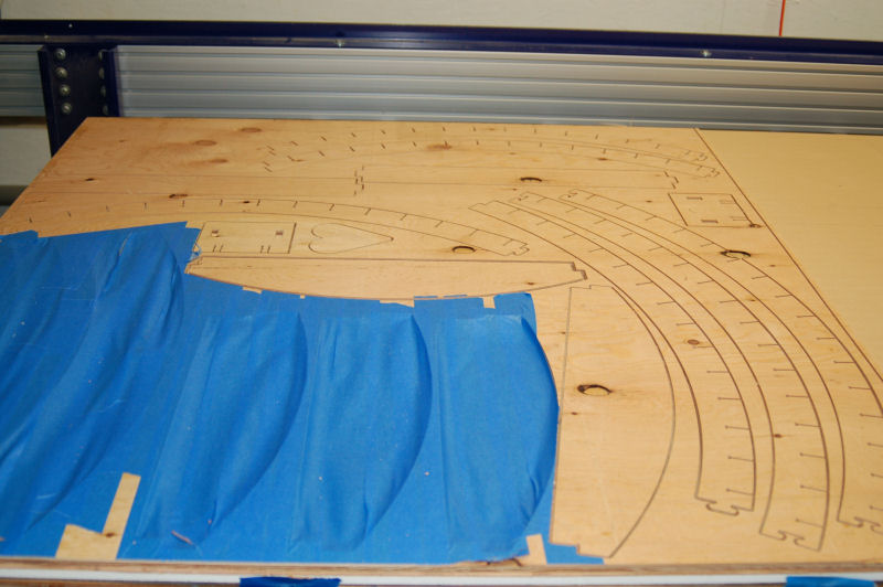
The parts on the table:
The blue tape masks off areas in the plywood that we'd cut the prior screen from. I use vacuum to hold raw material down to the table on the ShopBot and the blue tape makes sure there are no "leaks" through the open spaces in the plywood.
You'll notice that the screen parts are broken up into multiple sections - this is done to optimize material use. Wayne added "puzzle" ends to the parts that make up the arc in order to assemble them back into the full sized arc later.
This is what the joint looks like up close:
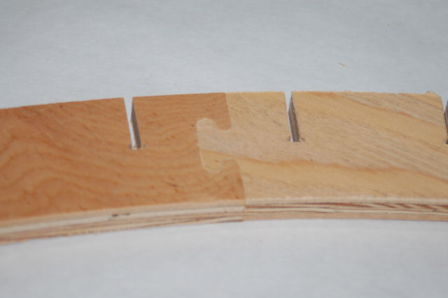
The tolerances are VERY tight with this. In order to create the slots for the 1/8" ribs, I had to tell VCarve Pro that the bit was .124" in diameter. This allowed the tool path to be properly created but it made the end-joints pretty tight.
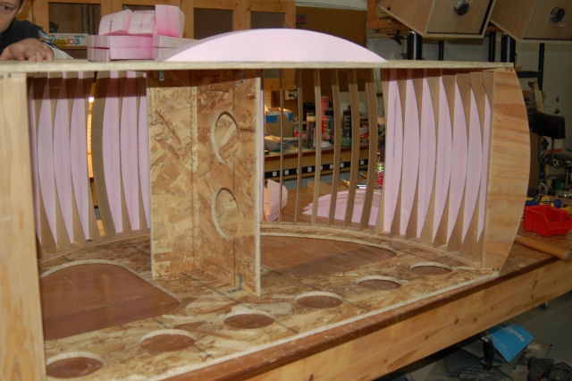
The parts shown on the table above, in combination with some others not shown will create the screen shown below:
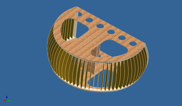
In between each of those ribs will be a foam wedge that will be used to fill the space in order to give the screen its shape. This requires a LOT of little foam blanks...
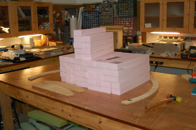
This is but a small fraction of the blocks I cut on the table saw. Each block was cut down to 3" by 21" and then cut again with a 2.5 degree angle. I counted my fingers every time my hand went by that screaming 10" saw blade.
The screen construction started by mounting the rib alignment ring with the base plate.
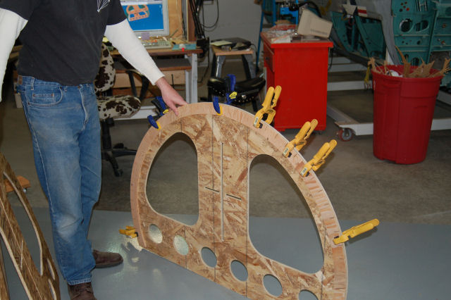
After the rib alignment rings were installed, the top & bottom plates were mated together using a "T" structure:
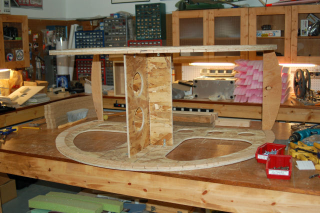
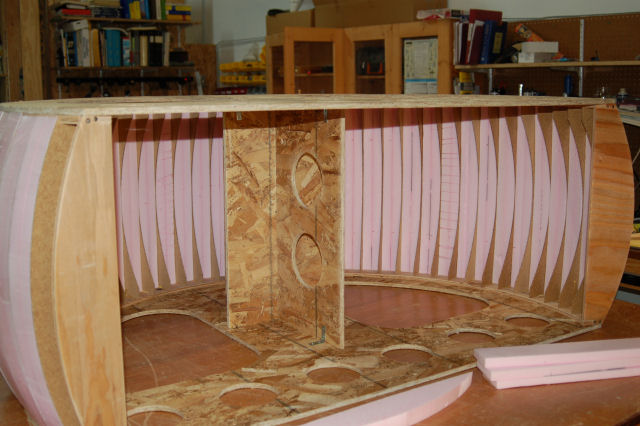
In order to form the shape needed for the screen, 44 1/8" ribs were installed. Between each rib is a hot-wire cut section of foam block.
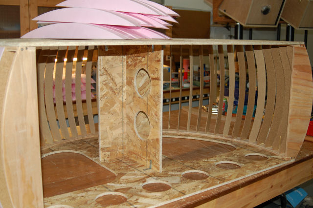
As each slot was filled, the fit got better and better as what little slack present was eliminated by each subsequent filler block.
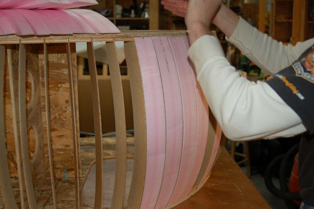
After some sanding, the end result was very, very nice!
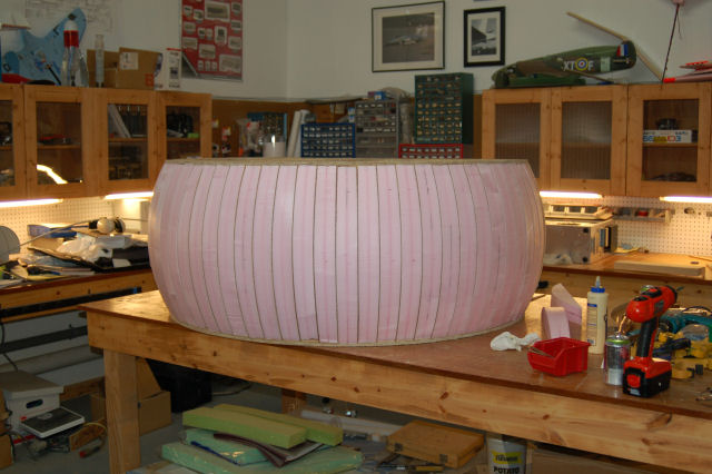
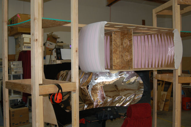
The screen was then skinned using a very light weight white fabric. When stretched across the framework, you can easily see the pink foam and brown dividing ribs. This gave rise to a number of Neapolitan jokes on my part.
One of the other tasks we got done on Saturday was to get the extra material on the mirror support ring trimmed off. We also got the non-usable portions of the mirror masked off with flat black paint.
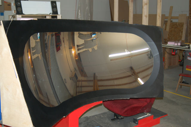
The result is great! There was some concern about the small amount of glue band with the additional material removed, but this proved to be un-founded. Fortunately.
Another odd thing we discovered - the mirror reflects IR VERY well. When moving around the front of the mirror, my hand reached a point where it was perfectly reflecting the heat coming from the pellet stove I have in the corner. My hand got really warm, really fast. Wayne & I spent the next 15 minutes experimenting with that little "feature". :)
Here's the rig set up for use:
Since the screen no longer had the huge band at the bottom, it became possible to slide it further back on the mounting platform so I could install my CH yoke on the frame. The Momo Racing wheel I have will fit as well. You may also notice that I took down the 15' screen. No longer needed.
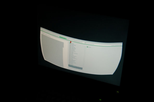
In case you were curious as to what NThusim did to the output, below is what the screen looks like at the console. The sim running at the moment is X-Plane.
Thank you all for reading - more news as it comes in!
Gene.