
I'd like to welcome you to the project site of the world's first DIY Collimated Cross-Cockpit Display.
I'm going to keep things short as we're still in the process of completing the project, but some day I hope to be able to provide details on how we did it!
The following two pages show the prototype mirror. These pages were created quickly and aren't that well organized:
Page 1
- Initial build, testing with very small, basic screen
Page 2 -
Construction of the large screen.
I made one glaring mistake when finishing the large screen - I didn't paint it before I applied the fabric. The end result was you could see wide bands of the pink foam separated by thin bands of brown where the ribs were. Combined with the white fabric, it looked like some kind of bizarre Neapolitan ice cream. Painting the fabric didn't help much as the weave was large enough to require a LOT of paint to fill up. It worked well enough for testing purposes though. If anyone is curious, the screen weighed in at 44lbs before painting. The new screen _might_ tip out at 15lbs. I used Ultralight MDF in the framing instead of OSB. Ultralight MDF is about 60% the weight of the "standard" MDF you'd find at places like Home Depot or Lowes.
The full sized mirror design didn't require much modification from the 60 degree version. I did inset the ribs by 1" in order to allow the mirror to form without worrying about the Mylar coming into contact with them.
Here's the stack of parts that make up the mirror framework:
The parts marked "TOP PLATE" and "BOTTOM PLATE" are cutting jigs. When clamped in place on my band saw, it allowed us to create the proper bevel that the top & bottom plates needed.
Here's the bottom doubler components after cutting on the band saw:

The doublers are just two 3/4" layers laminated together. In the background you can see the top plates - they're made from 3, 3/4" layers.
The top & bottom doublers will provide a suitable surface for attaching the "goggle" mask that's the Mylar is attached to.
The whole thing gets mounted to a movable platform that has the base table attached to it. I just discovered that I don't have any really good pictures of the table without anything on it, so this rotated image will have to suffice. :)

The table base is made from three segments - two 47" wide left & right panels and a center section that's about 12" wide. The outside panels have 5, 2" steel caster wheels on them. Makes it VERY easy to move, but not so easy to steer. :)
Below is a shot of the mirror framework sitting on the table. Nothing was bolted together or attached to the table in this picture. It gives a good idea of the layout however.

The configuration of the full sized mirror
required that we come up with some kind of design that would support the screen
atop the mirror framework.
What we came up with is below:

The original prototype screen is clamped in place - the new screen will have the same profile as the one shown above as opposed to the much taller version we built prior to this. The new screen design fits better within the mirror geometry than does the larger one. The new screen covers the same 220 degree arc as the old one, but only covers a 40 degree horizontal arc. The older screen covered probably close to 60 or 70 degrees.
Here's what the new screen looks like when mounted on the "spider" framework:
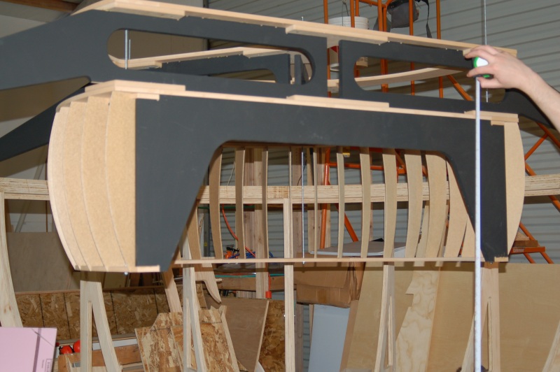
If you look closely, you'll see one of the four threaded steel rods that we use to hang the screen in place with. It's simple #10 threaded rod, but it works very well. Later on in the build I epoxied "T" nuts into the bottom of the frame to eliminate the nuts used prior. Keeps things cleaner and eliminates a snag point.
Here's a short video that shows a time-lapse of the screen being assembled: http://www.youtube.com/f15sim#p/u/4/t7553ZkkPXY.

To avoid the whole Neapolitan effect this time around, we coated the screen with a thin layer of filler. This helps remove the "polygon" shape that the spaces between the ribs create as well as gives us a way to more precisely control the shape. After a couple of more finish passes was made on this, it was painted using Behr Silver Screen paint. It works amazingly well! If you look closely at the original screen that's in the background, you can still see the vertical lines left by the ribs - I gave up after the 4th coat of Killz White primer.
One of the issues we dealt with in the prototype mirror was the huge number of air leaks we had to deal with. The new framework was built by making sure to gasket each segment and to put gasket material wherever there was a seam on the "wrong side" of the Mylar. The material I used was a 1/32" single-sided adhesive gasket that I got from All-Star Adhesives. This is the same material I used to insulate the vacuum zones on the ShopBot with. It's great stuff.
Each of the three primary mirror segments have their own back panel made from 1/8" hardboard. Fortunately we were able to use the ShopBot to pilot drill and countersink all the screw holes, otherwise it would have been a total nightmare! There's a ton of 3/4" screws in each panel..

When installing these, I used a gadget called a self-centering pilot drill. It's normally used on things like hinges to make sure your pilot hole is in the exact center of the thing you're going to mount.
 As you can see, it's a a pretty simple device, but it makes pilot hole alignment
very hard to get wrong!
As you can see, it's a a pretty simple device, but it makes pilot hole alignment
very hard to get wrong!
After getting the back installed, we next did a test fitting of the goggle mask:

FYI, we call it a "goggle" mask because when laid flat, its outline has the same appearance as a pair of ski goggles or a diving mask.
This mask was made from 3/16" hardboard and was assembled from six components. The two "ear" caps and two parts each for the top and bottom. This mask gives us a 3" wide band to apply the double-sided tape that we used to attach the mirror. (I should note that after experiencing the aggressiveness of the tape I chose, we could reasonably reduce the width of the mask down to about an inch and a half and still have it be perfectly adequate)
Before we mounted the goggle mask permanently, I installed a gasket band around the bottom perimeter of the mirror shape in order to help block air leaks:

In order to control the shape of the mirror on a consistent basis, Wayne developed a circuit that used an IR LED and an IR transistor pair in order to produce a 0..5V signal depending on how much reflected IR light the sensor saw. In this manner we could control a servo valve via an Arduino Duemilanove to manage the amount of bleed air we introduced into the vacuum system. Our first steps towards this control system can be seen in this video: http://www.youtube.com/f15sim#p/u/8/QC7H61palXs.
Another issue we wanted to address is over-drawing the mirror. The Mylar used in the full size version is 1mil or about .025mm thick. It won't take much stress past its strain point before it pops. It's not that expensive to replace if it does, but it takes a while to install. In order to detect when the Mylar reaches the "failsafe" point, I installed some copper tinsel. The tinsel is normally used in anti-static settings, but it works perfectly for us.

Because the Mylar we use is silvered on both sides, it will complete a circuit when it comes into contact with both tinsel pads. The copper tinsel is extremely flexible and won't harm the Mylar surface like an ordinary solid contact would.
The photo below shows the position of the IR sensor.

One of the major concerns we hit with the prototype mirror is the amount of sound it produces all by itself. In order to help dampen that out, we installed some 2" open cell foam in each frame bay:

Just standing in front of it and talking gives you an idea of the sound absorption of it. This in combination with much better air leak control should give us a virtually silent mirror. The photo above also shows the goggle mask installed. More screws. :)
After the double-sided tape was installed, we started getting the Mylar laid down...

We used rubber gloves at first in order to make sure we didn't mar the Mylar or leave any fingerprints on it.

If you look closely at Wayne's right hand, you'll notice a cloth mitt. This is normally used when applying Monokote (a thin-film heat shrink covering) to a model airplane wing or other part. It's very, very soft and won't mar the Mylar or scratch it. Using the mitt he could press the Mylar against the double-sided tape as I removed the tape film from the other side.
Here's the final shot before trimming:

The above picture really demonstrates the whole "conic section" issue with this setup. Because of how the Mylar must fit the conic section that's defined by the framework shape, we're unable to build a mirror frame that's greater than 8ft in diameter. The limitation is the commercial availability of Mylar in rolls wider than 54".
The photo below shows the Mylar after trimming. Standing in front of it gives a pretty amusing "fun-house" effect. :)

The photo above was taken at roughly 2:30am on Sunday the 5th of June, 2011. We were VERY tired and just about everything was funny at that point - I'd been up for 22 hours and Wayne wasn't that far behind me. All the sleep deprivation in the world was worth it when we saw the mirror draw-down for the first time.

Yeah, it's a dumb joke but it pretty much encapsulates the goofyness we were experiencing at the time. :) Here's the video I shot of the first draw-down process. There were no controls or failsafes installed at this point. We just HAD to see it go. http://www.youtube.com/watch?v=Vq30JMknmpg&feature=player_profilepage
Here's a short walk-around video that shows the current (09Jun11) state of the simulator: http://www.youtube.com/watch?v=wdr0-PVqjMk. Barring any unforseen issues we should be able to get all three projectors and their matching fold mirrors mounted on this coming Saturday (11Jun11).
Update: 29Jun11
This last Saturday was a disaster from the start. First I ruin some parts on the ShopBot when the some of the smaller parts I was cutting moved, then I snap a 1/4" cutter when another small part gets caught by the cutter.... (it gets worse)
In order to make sure we have a good seal, we decided to flip the mirror cell upright in order to seal the underside.


You'd be amazed at how well Latex Caulk works for stuff like this. :)
One of the issues we found on the first draw-down was the back sheeting. It wasn't stiff enough against the atmospheric pressure being applied to it.
We needed to stiffen it up in order for it to not partially collapse along the mirror cell segment seams. Unfortunately, during the installation of the last frame, it got away from me and I punched a hole in the mirror. *cringe*

I was very impressed with Wayne - he didn't yell at me once. Unfortunately, replacing the mirror cost us enough time that we were unable to get the system up and running by the time he had to leave.

We're getting pretty good at applying the Mylar. As aggressive as the tape we're using is, we could probably afford to use 1/2 the thickness. Right now the tape band is 3" wide. A 1 or 1.5" band would likely do the same job. Below shows the new mirror drawn down.

I was able to get the projectors installed and all wired up to the Digital Triple Head 2 Go that was donated by Matt over at mycockpit.org. Thanks Matt! (I'd actually referred to him as "Mike" in the progress report video linked below. *facepalm*)

I'm using three Epson 705HD projectors for this build - they're 1280x800 projectors. Very nice and they weren't too expensive either!
Here's the spider mounted atop the mirror cell:

All three fold mirrors are installed as well. Can you spot them? :)
Tragedy strikes... http://www.youtube.com/watch?v=D89fV-6b1pk
Status update video: http://www.youtube.com/watch?v=j3FvFx9z2R8
Next update will cover getting the projectors and fold mirrors aligned after the screen has been re-installed. Until then!
Update: 24Sep11
Hey folks, sorry for the long delay in updates. When you're using this thing, you tend to forget things. *laughs* Here's a video that I took of my friend Dave playing Need for Speed: Shift on the complete display: http://www.youtube.com/watch?v=_cyJIGII6JESome time later, Wayne did a nice video of the whole rig while I waited at
Friday Harbor in the FSX Grumman Goose.
http://www.youtube.com/watch?v=4R2bcZ-3eX8
Today I uploaded a video that I took last weekend of the controller we've developed that manages the mirror shape in real-time: http://www.youtube.com/watch?v=q309MyEtc3A
Right now we're dealing with some really annoying adhesive problems - mostly due to surface damage when we had to replace the mirror. I don't anticipate this being much of a problem long-term.
Update: 31Oct12
It's been a really long time since I did an update and I apologize for that! Lung cancer has this nasty way of slowing you down at times. Fortunately I beat it and I'm back at this and other projects.In August, we moved the display to its new home over at Wayne's house. We decided to transport it fully assembled after we'd replaced the Mylar on the mirror cell.
One of the things we found out is that the adhesive on the tape we were using will "creep" over time once it warms up and is under shear stress. This resulted in the Mylar sliding free of the framework and essentially ruining the image. In order to fix this, we decided to place a set of clamps around the perimeter of the mirror and adhere them with an additional layer of tape as well as screws.
Here's what the new clamp system looks like:

This method REALLY works well! There's no more worry about the adhesive failing and the black border formed by the clamps really gives the mirror cell a nice finished look.
One of the things I learned over the past winter is how the mirror shape is actively managed in commercial displays. As it turns out, there are two schools of thought on it - one group of manufacturers use a bleed-air valve like we started with, and the other group uses a rate controller on their vacuum pumps.
We decided to try the speed control method on our setup to see how it would work out. I went ahead and laser cut a set of gears that would allow us to drive a router speed controller I had handy.

We were amazed at how much easier it was to control the mirror this way!
Not only was it a LOT easier to stop the "breathing" issues we had with the
bleed-air box, but it was probably 70% quieter. The Fein dust collector was
ticking over at a very low RPM and keeping the mirror perfectly positioned.
Wayne brought over his Rigid shop vac and the result was pretty much the same.
The Rigid didn't have the sound dampening that the Fein has, but it was still
possible to have a conversation right next to the shop vac without having to
raise your voice!
Now that the display is essentially complete, I decided to give Wayne the first one instead of making him wait to get the second one built. The project has taken a lot longer than we expected and I didn't think it was fair to make him wait even longer to get a second display constructed. In August we transported the whole display over to his house.
In order to make sure that the mirror cell didn't twist while we were moving it, we attached a quarter sheet of OSB to the back to stiffen the whole thing up. If it were to twist, it could very easily tear the Mylar.

Here's what it looked like, ready to go (sans cover & straps):

It was a very nerve wracking trip. I was worried constantly about the moving air causing the Mylar to "flap" and cause it to fail. Fortunately, this didn't happen! I'll post pictures of the display set up at Wayne's when I get a chance to get over there and get some taken.
So what's next? Well right now I'm working on finishing the design for a 737 sized display for a friend in Colorado. It's HUGE. Measuring across the outside dimension of the mirror cell, it's 196" wide! The mirror cell ribs are about 62" high and the "blades" that form the shape of the screen are over 30" tall! He's got one hell of a construction project ahead of him. :)
Once the 737 display is done, I'm going to make a design change to the mirror cell rib shape on the original design and get mine built. I can't wait to get that sucker done so I can quit fiddling with it and just enjoy it! :)